Arduino Halloween Decoration
Arduino Halloween Decoration
So, my first foray into the world of Arduino and electronics is a simple motion sensing, light up Halloween decoration. Simple. This is my adventure creating it.
The Decoration
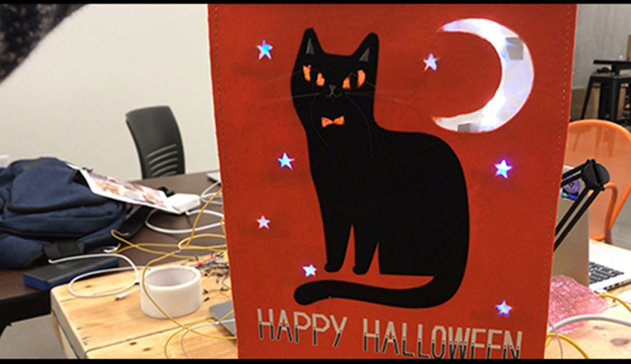
I randomly found this decoration while shopping for groceries. It was festive, the season was approaching, it was cheap and I like cats so I grabbed it. I had no intentions of it being used for my first Arduino learning experience.

Once the world of Arduino was revealed to me I looked at the decoration in an entirely new way. Wouldn’t it be cool if the eyes, stars, moon and bowtie all lit up when someone walked by? Yes. Yes it would be cool.
Preparing the Decoration
To get everything ready first I had to cut out the spots that would light up. A razor blade made quick work of it. Next I took blue, orange, and white tissue paper and hot glued it to the back of each hole.

This let’s light diffuse through more evenly.
That was the easy part. Now onto figuring out the electronics side of it.
The Components
This is what I would need to make my decoration light up to motion:
- Arduino Uno
- PIR Motion Sensor
- 2 Super Bright White LEDs
- 7 Blue LEDs
- 3 Yellow LEDs
- 24 12” lengths of jumper wire
The Arduino Uno, LEDs and jumper wire was all already available in the shop but the motion sensor had to be bought from Sparkfun.
All components assembled, now to figure out how to get the motion sensor to control the lights.
The Circuit: Phase 1
For my first attempt at using the PIR Motion sensor to light up some LEDs I just started with one. There is a lot of great documentation but I chose to start with the documentation on Sparkfun’s Site.
The example circuit they provided was perfect fo getting me started.

And the example code (pulled from Sparkfun) did exactly what I needed it to do:
PIR_Motion_Detector_Example.ino
Example sketch for SparkFun's PIR Motion Detector
  (https://www.sparkfun.com/products/13285)
Jim Lindblom @ SparkFun Electronics
May 2, 2016

The PIR motion sensor has a three-pin JST connector terminating it. Connect
the wire colors like this:
- Black: D2 - signal output (pulled up internally)
- White: GND
- Red: 5V

Connect an LED to pin 13 (if your Arduino doesn't already have an LED there).

Whenever the PIR sensor detects movement, it'll write the alarm pin LOW.

Development environment specifics:
Arduino 1.6.7
******************************************************************************/
const int MOTION_PIN = 2; // Pin connected to motion detector
const int LED_PIN = 13; // LED pin - active-high

void setup()
{
  Serial.begin(9600);
  // The PIR sensor's output signal is an open-collector,
  // so a pull-up resistor is required:
  pinMode(MOTION_PIN, INPUT_PULLUP);
  pinMode(LED_PIN, OUTPUT);
}

void loop()
{
  int proximity = digitalRead(MOTION_PIN);
  if (proximity == LOW) // If the sensor's output goes low, motion is detected
  {
    digitalWrite(LED_PIN, HIGH);
    Serial.println("Motion detected!");
  }
  else
  {
    digitalWrite(LED_PIN, LOW);
  }
}
I was able to light up a single LED successfully when I moved. My first success!
SimpleSensorCircuit from Jim Murphy on Vimeo.
Now I just need to add in more lights.
The Circuit: Phase 2
S*!t
It seems that while three LEDs are able to light up any more than that and they begin to dim or not light up at all.
Back to Google. Several long Google searches later and a message to my professor all came back with the same info.
Resistors
I need to have resistors in parallel to distribute the power to each LED. Once again, Sparkfun provided the perfect tutorial and example code to get me going.
I assembled my Arduino and lights just like the image showed.

Uploaded the code on the Sparkfun Experiment site and voila!
DancingLEDs from Jim Murphy on Vimeo.
Ok, my lighting circuit is successful. Now I just need to figure out how to combine the code I used to control one LED with the motion sensor with the code I used to power multiple LEDs.
The Code
I knew how to design the circuit. But the code would prove to be the most difficult part of this project.
The Two Codes
Here are the following two pieces of code from Sparkfun that I needed to combine.
Control One LED with PIR Motion Sensor
PIR_Motion_Detector_Example.ino
Example sketch for SparkFun's PIR Motion Detector
  (https://www.sparkfun.com/products/13285)
Jim Lindblom @ SparkFun Electronics
May 2, 2016

The PIR motion sensor has a three-pin JST connector terminating it. Connect
the wire colors like this:
- Black: D2 - signal output (pulled up internally)
- White: GND
- Red: 5V

Connect an LED to pin 13 (if your Arduino doesn't already have an LED there).

Whenever the PIR sensor detects movement, it'll write the alarm pin LOW.

Development environment specifics:
Arduino 1.6.7
******************************************************************************/
const int MOTION_PIN = 2; // Pin connected to motion detector
const int LED_PIN = 13; // LED pin - active-high

void setup()
{
  Serial.begin(9600);
  // The PIR sensor's output signal is an open-collector,
  // so a pull-up resistor is required:
  pinMode(MOTION_PIN, INPUT_PULLUP);
  pinMode(LED_PIN, OUTPUT);
}

void loop()
{
  int proximity = digitalRead(MOTION_PIN);
  if (proximity == LOW) // If the sensor's output goes low, motion is detected
  {
    digitalWrite(LED_PIN, HIGH);
    Serial.println("Motion detected!");
  }
  else
  {
    digitalWrite(LED_PIN, LOW);
  }
}
Make Multiple LEDs Dance
/*
SparkFun Inventor's Kit
Example sketch 04

MULTIPLE LEDs

  Make eight LEDs dance. Dance LEDs, dance!

Hardware connections:

  You'll need eight LEDs, and eight 330 Ohm resistors
  (orange-orange-brown).

    For each LED, connect the negative side (shorter leg)
    to a 330 Ohm resistor.

    Connect the other side of the resistors to GND.

    Connect the positive side (longer leg) of the LEDs
    to Arduino digital pins 2 through 9.

This sketch was written by SparkFun Electronics,
with lots of help from the Arduino community.
This code is completely free for any use.
Visit http://learn.sparkfun.com/products/2 for SIK information.
Visit http://www.arduino.cc to learn about the Arduino.

Version 2.0 6/2012 MDG
*/


// To keep track of all the LED pins, we'll use an "array".
// An array lets you store a group of variables, and refer to them
// by their position, or "index". Here we're creating an array of
// eight integers, and initializing them to a set of values:

int ledPins[] = {2,3,4,5,6,7,8,9};

// The first element of an array is index 0.
// We've put the value "2" in index 0, "3" in index 1, etc.
// The final index in the above array is 7, which contains
// the value "9".

// We're using the values in this array to specify the pin numbers
// that the eight LEDs are connected to. LED 0 is connected to
// pin 2, LED 1 is connected to pin 3, etc.


void setup()
{
  int index;

  // In this sketch, we'll use "for() loops" to step variables from
  // one value to another, and perform a set of instructions for
  // each step. For() loops are a very handy way to get numbers to
  // count up or down.

  // Every for() loop has three statements separated by
  // semicolons (;):

  //   1. Something to do before starting
  //   2. A test to perform; as long as it's true, keep looping
  //   3. Something to do after each loop (increase a variable)

  // For the for() loop below, these are the three statements:

  //   1. index = 0;    Before starting, make index = 0.
  //   2. index <= 7;   If index is less or equal to 7,
  //                    run the following code.
  //            (When index = 8, continue with the sketch.)
  //   3. index++   Putting "++" after a variable means
  //                    "add one to it".
  //            (You can also use "index = index + 1".)

  // Every time you go through the loop, the statements following
  // the for() (within the brackets) will run.

  // When the test in statement 2 is finally false, the sketch
  // will continue.


  // Here we'll use a for() loop to initialize all the LED pins
  // to outputs. This is much easier than writing eight separate
  // statements to do the same thing.

  // This for() loop will make index = 0, then run the pinMode()
  // statement within the brackets. It will then do the same thing
  // for index = 2, index = 3, etc. all the way to index = 7.

  for(index = 0; index <= 7; index++)
  {
    pinMode(ledPins[index],OUTPUT);
    // ledPins[index] is replaced by the value in the array.
    // For example, ledPins[0] is 2
  }
}


void loop()
{
  // This loop() calls functions that we've written further below.
  // We've disabled some of these by commenting them out (putting
  // "//" in front of them). To try different LED displays, remove
  // the "//" in front of the ones you'd like to run, and add "//"
  // in front of those you don't to comment out (and disable) those
  // lines.

  oneAfterAnotherNoLoop();  // Light up all the LEDs in turn

  //oneAfterAnotherLoop();  // Same as oneAfterAnotherNoLoop,
                            // but with much less typing

  //oneOnAtATime();         // Turn on one LED at a time,
                            // scrolling down the line

  //pingPong();             // Light the LEDs middle to the edges

  //marquee();              // Chase lights like you see on signs

  //randomLED();            // Blink LEDs randomly
}


/*
oneAfterAnotherNoLoop()

This function will light one LED, delay for delayTime, then light
the next LED, and repeat until all the LEDs are on. It will then
turn them off in the reverse order.

This function does NOT use a for() loop. We've done it the hard way
to show you how much easier life can be when you use for() loops.
Take a look at oneAfterAnotherLoop() further down, which does
exactly the same thing with much less typing.
*/

void oneAfterAnotherNoLoop()
{
  int delayTime = 100; // time (milliseconds) to pause between LEDs
                       // make this smaller for faster switching

  // turn all the LEDs on:

  digitalWrite(ledPins[0], HIGH);  //Turns on LED #0 (pin 2)
  delay(delayTime);                //wait delayTime milliseconds
  digitalWrite(ledPins[1], HIGH);  //Turns on LED #1 (pin 3)
  delay(delayTime);                //wait delayTime milliseconds
  digitalWrite(ledPins[2], HIGH);  //Turns on LED #2 (pin 4)
  delay(delayTime);                //wait delayTime milliseconds
  digitalWrite(ledPins[3], HIGH);  //Turns on LED #3 (pin 5)
  delay(delayTime);                //wait delayTime milliseconds
  digitalWrite(ledPins[4], HIGH);  //Turns on LED #4 (pin 6)
  delay(delayTime);                //wait delayTime milliseconds
  digitalWrite(ledPins[5], HIGH);  //Turns on LED #5 (pin 7)
  delay(delayTime);                //wait delayTime milliseconds
  digitalWrite(ledPins[6], HIGH);  //Turns on LED #6 (pin 8)
  delay(delayTime);                //wait delayTime milliseconds
  digitalWrite(ledPins[7], HIGH);  //Turns on LED #7 (pin 9)
  delay(delayTime);                //wait delayTime milliseconds

  // turn all the LEDs off:

  digitalWrite(ledPins[7], LOW);   //Turn off LED #7 (pin 9)
  delay(delayTime);                //wait delayTime milliseconds
  digitalWrite(ledPins[6], LOW);   //Turn off LED #6 (pin 8)
  delay(delayTime);                //wait delayTime milliseconds
  digitalWrite(ledPins[5], LOW);   //Turn off LED #5 (pin 7)
  delay(delayTime);                //wait delayTime milliseconds
  digitalWrite(ledPins[4], LOW);   //Turn off LED #4 (pin 6)
  delay(delayTime);                //wait delayTime milliseconds
  digitalWrite(ledPins[3], LOW);   //Turn off LED #3 (pin 5)
  delay(delayTime);                //wait delayTime milliseconds
  digitalWrite(ledPins[2], LOW);   //Turn off LED #2 (pin 4)
  delay(delayTime);                //wait delayTime milliseconds
  digitalWrite(ledPins[1], LOW);   //Turn off LED #1 (pin 3)
  delay(delayTime);                //wait delayTime milliseconds
  digitalWrite(ledPins[0], LOW);   //Turn off LED #0 (pin 2)
  delay(delayTime);                //wait delayTime milliseconds
}


/*
oneAfterAnotherLoop()

This function does exactly the same thing as oneAfterAnotherNoLoop(),
but it takes advantage of for() loops and the array to do it with
much less typing.
*/

void oneAfterAnotherLoop()
{
  int index;
  int delayTime = 100; // milliseconds to pause between LEDs
                       // make this smaller for faster switching

  // Turn all the LEDs on:

  // This for() loop will step index from 0 to 7
  // (putting "++" after a variable means add one to it)
  // and will then use digitalWrite() to turn that LED on.

  for(index = 0; index <= 7; index++)
  {
    digitalWrite(ledPins[index], HIGH);
    delay(delayTime);
  }

  // Turn all the LEDs off:

  // This for() loop will step index from 7 to 0
  // (putting "--" after a variable means subtract one from it)
  // and will then use digitalWrite() to turn that LED off.

  for(index = 7; index >= 0; index--)
  {
    digitalWrite(ledPins[index], LOW);
    delay(delayTime);
  }
}


/*
oneOnAtATime()

This function will step through the LEDs,
lighting only one at at time.
*/

void oneOnAtATime()
{
  int index;
  int delayTime = 100; // milliseconds to pause between LEDs
                       // make this smaller for faster switching

  // step through the LEDs, from 0 to 7

  for(index = 0; index <= 7; index++)
  {
    digitalWrite(ledPins[index], HIGH);  // turn LED on
    delay(delayTime);                    // pause to slow down
    digitalWrite(ledPins[index], LOW);   // turn LED off
  }
}


/*
pingPong()

This function will step through the LEDs,
lighting one at at time in both directions.
*/

void pingPong()
{
  int index;
  int delayTime = 100; // milliseconds to pause between LEDs
                       // make this smaller for faster switching

  // step through the LEDs, from 0 to 7

  for(index = 0; index <= 7; index++)
  {
    digitalWrite(ledPins[index], HIGH);  // turn LED on
    delay(delayTime);                    // pause to slow down
    digitalWrite(ledPins[index], LOW);   // turn LED off
  }

  // step through the LEDs, from 7 to 0

  for(index = 7; index >= 0; index--)
  {
    digitalWrite(ledPins[index], HIGH);  // turn LED on
    delay(delayTime);                    // pause to slow down
    digitalWrite(ledPins[index], LOW);   // turn LED off
  }
}


/*
marquee()

This function will mimic "chase lights" like those around signs.
*/

void marquee()
{
  int index;
  int delayTime = 200; // milliseconds to pause between LEDs
                       // Make this smaller for faster switching

  // Step through the first four LEDs
  // (We'll light up one in the lower 4 and one in the upper 4)

  for(index = 0; index <= 3; index++) // Step from 0 to 3
  {
    digitalWrite(ledPins[index], HIGH);    // Turn a LED on
    digitalWrite(ledPins[index+4], HIGH);  // Skip four, and turn that LED on
    delay(delayTime);                      // Pause to slow down the sequence
    digitalWrite(ledPins[index], LOW);     // Turn the LED off
    digitalWrite(ledPins[index+4], LOW);   // Skip four, and turn that LED off
  }
}


/*
randomLED()

This function will turn on random LEDs. Can you modify it so it
also lights them for random times?
*/

void randomLED()
{
  int index;
  int delayTime;

  // The random() function will return a semi-random number each
  // time it is called. See http://arduino.cc/en/Reference/Random
  // for tips on how to make random() even more random.

  index = random(8);    // pick a random number between 0 and 7
  delayTime = 100;

  digitalWrite(ledPins[index], HIGH);  // turn LED on
  delay(delayTime);                    // pause to slow down
  digitalWrite(ledPins[index], LOW);   // turn LED off
}
After examining both I identified the key elements from the dancing LEDs code that I could plug into the motion sensor code.
First, I needed to create an array, assigning all the Pins with an LED in them to the variable ledPins.
ledPins[] = {2,3,4,5,6,7,8,9,10,11,12};
Also, since I needed all 12 digital pins for my LEDs, I needed to change the Motion sensor variable from MOTION_PIN = 2 to MOTION_Pin = 13.
My first draft code looked like this:
/******************************************************************************
PIR_Motion_Detector_Halloween_Decoration.ino
Sketch for Critical Making Project
Jim Murphy @ BDW Studio
October, 9 2018
Based on example sketches from Sparkfun.com
******************************************************************************/
const int MOTION_PIN = 13; // Pin connected to motion detector
const int ledPins[] = {2,3,4,5,6,7,8,9,10,11,12}; // LED pin - active-high

void setup()
{
  Serial.begin(9600);
  // The PIR sensor's output signal is an open-collector,
  // so a pull-up resistor is required:
  pinMode(MOTION_PIN, INPUT_PULLUP);
  pinMode(ledPins[0,1,2,3,4,5,6,7,8,9,10,11], OUTPUT);
}

void loop()
{
  int proximity = digitalRead(MOTION_PIN);
  if (proximity == LOW); // If the sensor's output goes low, motion is detected
  {
    digitalWrite(ledPins[0,1,2,3,4,5,6,7,8,9,10,11], HIGH);
  }
  else
  {
    digitalWrite(ledPins[0,1,2,3,4,5,6,7,8,9,10,11], LOW);
  }
}
I plugged this into the IDE and hit go…nothing.
Double S&$t!
Back to the code.
I reviewed the the two codes and determined that the problem was with the ledPins variable. My syntax must be wrong when defining OUTPUT and digitalWrite. I still wasn’t sure which syntax to use but I figured that if I made and OUTPUT and digitalWrite commands for each ledPin then that would work. My next iteration of code looked like this:
/******************************************************************************
PIR_Motion_Detector_Halloween_Decoration.ino
Sketch for Critical Making Project
Jim Murphy @ BDW Studio
October, 9 2018
Based on example sketches from Sparkfun.com
******************************************************************************/
const int MOTION_PIN = 13; // Pin connected to motion detector
const int ledPins[] = {2,3,4,5,6,7,8,9,10,11,12}; // LED pin - active-high

void setup()
{
  Serial.begin(9600);
  // The PIR sensor's output signal is an open-collector,
  // so a pull-up resistor is required:
  pinMode(MOTION_PIN, INPUT_PULLUP);
  pinMode(ledPins[0], OUTPUT);
  pinMode(ledPins[1], OUTPUT);
  pinMode(ledPins[2], OUTPUT);
  pinMode(ledPins[3], OUTPUT);
  pinMode(ledPins[4], OUTPUT);
  pinMode(ledPins[5], OUTPUT);
  pinMode(ledPins[6], OUTPUT);
  pinMode(ledPins[7], OUTPUT);
  pinMode(ledPins[8], OUTPUT);
  pinMode(ledPins[9], OUTPUT);
  pinMode(ledPins[10], OUTPUT);
  pinMode(ledPins[11], OUTPUT);
  pinMode(ledPins[12], OUTPUT);
}

void loop()
{
  int proximity = digitalRead(MOTION_PIN);
  if (proximity == LOW) // If the sensor's output goes low, motion is detected
  {
    digitalWrite(ledPins[0], HIGH);
    digitalWrite(ledPins[1], HIGH);
    digitalWrite(ledPins[2], HIGH);
    digitalWrite(ledPins[3], HIGH);
    digitalWrite(ledPins[4], HIGH);
    digitalWrite(ledPins[5], HIGH);
    digitalWrite(ledPins[6], HIGH);
    digitalWrite(ledPins[7], HIGH);
    digitalWrite(ledPins[8], HIGH);
    digitalWrite(ledPins[9], HIGH);
    digitalWrite(ledPins[10], HIGH);
    digitalWrite(ledPins[11], HIGH);
    digitalWrite(ledPins[12], HIGH);
    delay (5000);

  }
  else
  {
    digitalWrite(ledPins[0], LOW);
    digitalWrite(ledPins[1], LOW);
    digitalWrite(ledPins[2], LOW);
    digitalWrite(ledPins[3], LOW);
    digitalWrite(ledPins[4], LOW);
    digitalWrite(ledPins[5], LOW);
    digitalWrite(ledPins[6], LOW);
    digitalWrite(ledPins[7], LOW);
    digitalWrite(ledPins[8], LOW);
    digitalWrite(ledPins[9], LOW);
    digitalWrite(ledPins[10], LOW);
    digitalWrite(ledPins[11], LOW);
    digitalWrite(ledPins[12], LOW);
    delay(500);
  }
}
With bated breath I hit that upload button…
Eureka! Github for this code
All Lights Working from Jim Murphy on Vimeo.
The Assembly
Now that my circuit and code were both correct I could focus on assembling the decoration. This was not going to be a beautifully polished project but it would work.
First I needed to solder the jumper cables to the lights.

Next, I needed to position each light on the back of the decoration and tape them down.

Now I needed to plug the other end of the jumper wires into the appropriate place on the breadboard.
Aahh, damn. I forgot to note which was the ground and which was the positive before I soldered the cables to the lights. Guess It’ll be guess and check.

Sensor is plugged in and everything looks ready to go.
Hit upload and…
about half work.
I quickly identify which aren’t and switch their wires. They immediately pop on as I move in front of the sensor.
All Working from Jim Murphy on Vimeo.
Boom!
Success, finally.
What I Learned & Improvements
What I learned
- Arduino Syntax
- Variables, Arrays, digitalWrite, OUTPUT
- How to drive multiples LEDs
- Use of resistors
- How to create a circuit using a sensor and LED lights
- How to research different components and their use
Improvements
- Syntax to make the lights on the stars blink (twinkle)
- Brighter LEDs
- LED light strip to make words light up